Design of Suitable Nozzle for Installation of Various Mixers
Tanks and vessels equipped with top entry or side entry mixers are subjected to various loads exerted by the agitators. These loads must be reported by the mixer manufacturer to the vessel designer to be applied in the nozzle design.
The tank nozzle should be designed such that the maximum deflection in any direction does not exceed 0.25 degrees.
Main loads Acting on Top-Entry and Side-Entry Mixers
Industrial mixers during operation are subjected to four main loads:
Dynamic Torque
Bending Moment
Static Load
Thrust Force
These loads arise from the interaction of the fluid flow with the rotating blades and depend on the operating conditions. For example, Weetman and Gigas in their paper[1] state that the forces exerted by the fluid on the impeller are directly transferred to the shaft and ultimately to the support.
Figure1: Main loads on Side-Entry and Top Entry mixers
Each of these loads is described below, influential factors are mentioned, and calculation formulas are provided.
1-Dynamic Torque
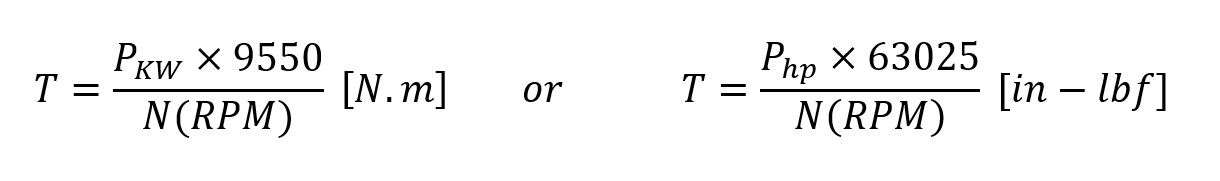
Due to the rotation of the impellers within the fluid, the mixer consumes a certain amount of power. The nominal dynamic torque can be calculated using the following formulas.
Considering the presence of moment of inertia, during startup, the instantaneous torque consumed by the mixer will be higher than the nominal torque. Therefore, the nozzle must be designed to withstand this torque. Typically, the design dynamic torque is taken as twice the nominal torque:
Figure 2: Dynamic torque due to propeller rotation
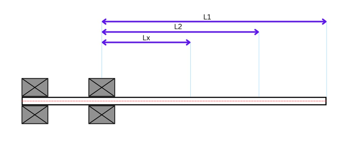
2-Bending Moment
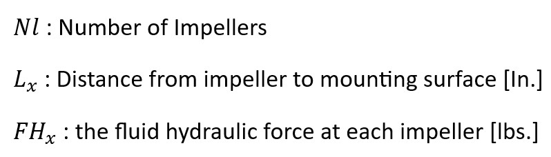
The bending moment is caused by the lateral (radial) force of the fluid on the blades, applied perpendicular to the shaft.
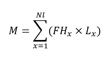
Simply put, the bending moment equals the product of the lateral hydrodynamic force FH and the lever arm L. Therefore, the total bending moment acting on the mixer is the resultant of the bending moments of each impeller:
Figure 3: Bending-Moment
3-Static Load
Generally, the static load equals the total weight force of the equipment. This force is the product of the total mass and gravitational acceleration:
with units in Newtons (N). This vertical load is mainly applied to the shaft support bearing.
Figure 4: Static Load
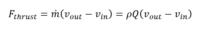
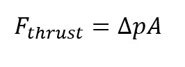
4-Thrust Force
Thrust force is the axial force applied to the shaft along the flow direction. This force results from the change in fluid momentum along the shaft axis and the pressure difference across the impeller. According to the momentum equation for the control volume:
where 𝝆 is fluid density, Q is volumetric flow rate, and V is axial fluid velocity. Thrust can also be expressed as a pressure difference:
where is the effective blade area. Factors such as fluid density, flow rate, and blade installation angle (the greater the axial velocity component, the higher the thrust) determine the magnitude of this force.