A Comprehensive Overview of Balancing in Rotating Equipment
A Comprehensive Overview of Balancing in Rotating Equipment
Studying this article will help answer the following questions:
What is unbalance?
What are the types of unbalances in rotating equipment?
What are the effects of unbalance on equipment?
What are the methods for balancing dynamic systems?
What is static unbalance?
What is dynamic unbalance?
Abstract
Balancing a rotating system (such as a car wheel, turbine, pump, fan, mixer blade, gear, etc.) is one of the most critical requirements for such equipment. Unbalance, or imbalance, occurs when:
The equipment is in motion or rotating;
The centrifugal forces are unevenly distributed and do not cancel each other out.
More precisely, in rotational motion, unbalance refers to a condition where the mass distribution of a rotating object around its axis of rotation is not uniform. This lack of uniformity generates uneven centrifugal forces during rotation, which can lead to vibrations, instability, or excessive stress in the system.
Unbalance is directly related to the displacement of the principal axes of inertia. In an ideal and symmetrical object, the principal axis of inertia passes through the center of gravity and aligns with the axis of rotation. However, in the presence of unbalance, the principal axes of inertia are displaced and no longer align with the axis of rotation. This occurs because the center of gravity shifts or the symmetry of the object is disrupted, causing the position or orientation of these axes to change. This displacement generates additional torques during rotation, leading to vibrations and mechanical issues in the system.
To eliminate unbalance, the mass distribution must be adjusted in such a way that the principal axis of inertia and the axis of rotation realign. This is typically achieved through balancing methods such as adding counterweights or removing mass.
It is important to note that not all vibrations in your equipment are necessarily due to unbalance. Vibrations can sometimes result from resonance, bearing failures, and other factors. The focus of this article is on vibrations caused by unbalance and the methods to address them.
Definitions
Center of Gravity: The center of gravity is the point in an object where the resultant torque due to the mass distribution of the object is zero. Simply put, it represents the balance point of the object.
Centrifugal Force: A virtual force that appears to act outward on a rotating object and is a result of the rotational motion. This quantity is observed whenever an object moves along a curved or circular path.
Moment of Inertia: The moment of inertia, or rotational inertia, is the resistance that objects exhibit when initiating circular motion.
Principal Axes of Inertia: These are the axes around which, if an object rotates:
– Firstly, the rotation occurs in a stable, uniform, and vibration-free manner.
– Secondly, no additional external torque (resulting from uneven mass distribution) is generated.
Principal Moments of Inertia: These are the values of the moment of inertia obtained when an object rotates around its principal axes of inertia. Mathematically, these moments represent the distribution of mass in all three-dimensional directions.
Introduction
Have you ever wondered why older washing machines vibrate excessively or why cars shake at certain speeds? All these phenomena occur due to a condition known as “unbalance”. This condition can occur in all dynamic equipment, particularly in rotating machinery. Unbalance, or imbalance, is essentially the uneven distribution of mass around the axis of rotation. The excess mass causing this imbalance generates centrifugal forces that remain unnaturalized, causing the entire object to deviate from its primary axis of rotation. Any unbalance manifests as vibration. Therefore, balancing rotors and rotating equipment prevents excessive stress on bearings and fatigue-related failures, ultimately extending the lifespan of the machinery.
Types of Unbalances
According to the definitions provided in the ISO 1925 standard, unbalance in rotating equipment is categorized into three main types:
1. Static Unbalance:
Static unbalance occurs when there is an excess mass at a specific radius, causing the center of gravity of the object to shift relative to its axis of rotation. This generates a centrifugal force that attempts to deflect the rotating object from its axis (as shown in Figure 1), resulting in vibration.
This type of unbalance can be identified by placing the rotating part on two supports. The heavier side will tend to move downward due to gravity.
To balance this system, an equal mass is placed directly opposite the excess mass at the same radius, restoring the center of gravity to its original position. This balancing method is commonly referred to as single-plane balancing.
Figure 1: Vibration caused by static imbalance and how to fix it
2. Couple (Moment) Unbalance:
As illustrated in Figure 2, this type of unbalance occurs when two equal masses are aligned in the transverse view but are positioned at a distance from each other in the longitudinal view, creating a couple unbalance.
Unlike static unbalance, in couple unbalance, the mass distribution cancels out in the static state. Therefore, gravitational force cannot move the rotating part when it is stationary.
Figure 2: Coupled imbalance
In engineering terms, the center of gravity of the object aligns with the axis of rotation, and static balance is maintained. However, the centrifugal forces generated by these two masses do not cancel each other out. Instead, they create a rotational moment (torque) around an axis perpendicular to the axis of rotation.
This type of unbalance can be corrected by adding or removing corrective masses in two planes (as shown in Figure 3).
Figure 3: Vibration caused by coupling imbalance and how to fix it
3. Dynamic Unbalance:
Dynamic unbalance (as shown in Figure 3) occurs when both static unbalance and couple unbalance are present simultaneously. In this case, the rotating equipment exhibits mass and centrifugal force imbalances across multiple planes.
To correct dynamic and couple unbalance, a digital balancing machine (as shown in Figure 4) is used. By measuring the machine’s vibrations during operation, the machine determines the specific angles and masses that need to be added or removed in two planes. This ensures that the resultant centrifugal forces are neutralized, and the equipment is properly balanced.
Figure 4: Vibration caused by dynamic imbalance and how to fix it
Figure 5: An example of a dynamic balance device
In summary, the most severe vibrations are caused by dynamic unbalance, while the intensity of vibrations from static unbalance and couple unbalance rank lower, respectively.
Another critical point regarding unbalance is the direct relationship between the system’s vibration levels and its rotational speed. As shown in the figure below, the higher the rotational speed of an unbalanced piece of equipment, the greater the vibrations and, consequently, the more damage it causes to the system. This is why, for example, if your car has an imbalance in its wheels or engine, it starts to vibrate significantly at speeds above 80 km/h, while at lower speeds, you may not notice any abnormal vibrations.
Figure 6: Relationship between rotational speed and vibration due to unbalance (stationary equipment has no vibration)
How to Calculate the Amount of Unbalance
The amount of unbalance is equal to the product of the excess mass and its radial distance from the axis of rotation. It is represented by U and can be calculated using the following formula:
This relationship is derived from the formula for calculating centrifugal force. We know that centrifugal force is calculated as follows:
Where:
Fc: Centrifugal force (in Newtons, N)
m: Mass (in kilograms, kg)
r: Radial distance of the mass from the axis of rotation (in meters, m)
ω (omega): Angular velocity (in radians per second, rad/s)
Why?
Because in rotating equipment, the angular velocity (rotational speed) is a fixed value. If there is no excess mass (i.e., m = 0) or if all excess masses are located precisely on the axis of rotation (i.e., r = 0), then no disruptive centrifugal force will be generated in the system.
Since mass is typically measured in grams (g) and distance in millimeters (mm), the unit of unbalance (U) is expressed as gram-millimeters (g· mm).
Therefore, once the amount of excess mass and its radial location are known, the unbalance of the equipment can be easily calculated using the formula:
Allowable Unbalance Limits in Rotating Equipment
As previously mentioned, balancing a rotating system can be achieved by adding or removing excess mass in one or two planes. However, in practice, it is impossible to eliminate unbalance entirely, and a small residual unbalance always remains in the system. The ISO 1940 standard addresses this by introducing a parameter called the Balance Quality Grade (G), which defines the allowable residual unbalance based on the type of equipment.
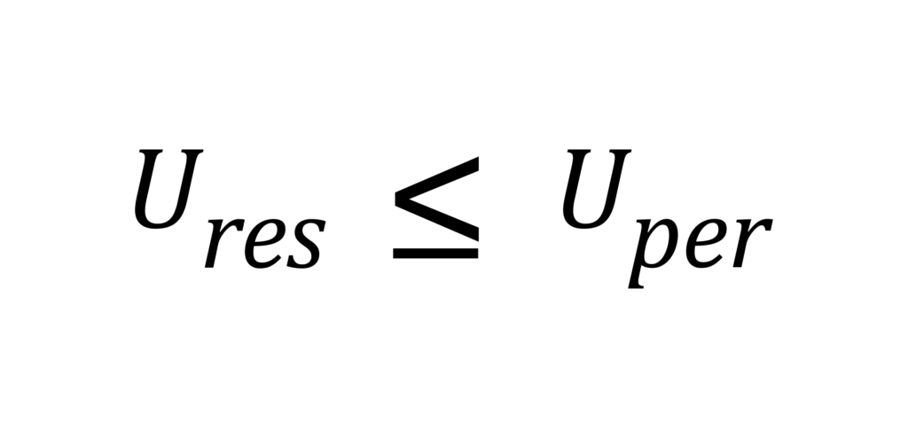
This standard specifies that the actual residual unbalance (Ures) in your equipment must always be less than the permissible unbalance (Uper)
Steps to calculate the permissible unbalance (U-per) in the equipment
When the mass, rotational speed, and balance quality grade of a piece of equipment are known, the permissible residual unbalance (Uper) can be calculated. This calculation forms the basis for both static and dynamic balancing machines.
Step 1: Determine the Balance Quality Grade (G) Based on the Equipment’s Application
According to ISO 1940, the balance quality grade for various types of equipment is specified based on their application and type. Table 1 in the standard provides the balance quality grades for different equipment categories.
For example:
G 0.4: Precision grinding machine spindles.
G 1.0: Gas and steam turbines, turbo compressors.
G 2.5: Automotive driveshafts, machine tool drives.
G 6.3: Pumps, fans, general machinery.
G 16.0: Agricultural machinery, crushers.
The balance quality grade (G) is expressed in millimeters per second (mm/s) and represents the maximum allowable vibration velocity due to unbalance.
Step 2: Determine the Rotational Speed of the Equipment During Operation
The rotational speed of the rotor around its axis is typically expressed in RPS (revolutions per second) or RPM (revolutions per minute). For example, a motor that completes one revolution per second has a rotational speed of 60 RPM.
Step 3: Measure the Weight of the Equipment in Kilograms
The total mass of the rotating equipment is measured in kilograms (kg). This value is essential for calculating the permissible unbalance.
Step 4: Determine the Parameter e<sub>per</sub> Using the Chart
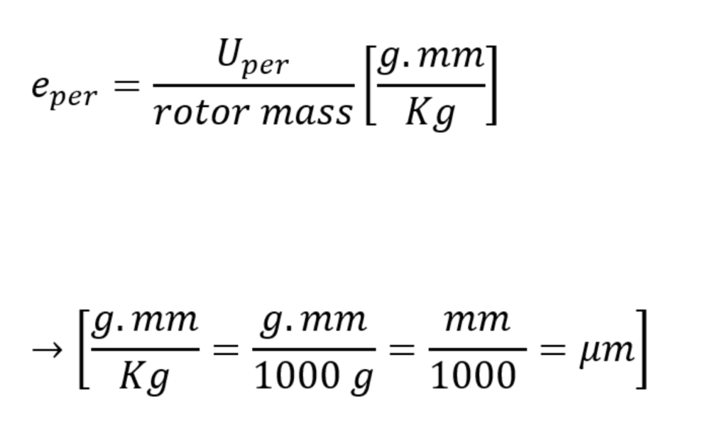
To determine the permissible unbalance, the parameter eperis introduced. This parameter represents the allowable unbalance per unit mass of the rotor (1 kg) and is calculated as follows:
In fact, this parameter essentially represents the maximum allowable radial distance (in micrometers, µm) between the center of gravity of the rotor and its axis of rotation.
Next, using the chart below, in accordance with the ISO 1940 standard, the value of Eper can be determined based on the rotational speed of the equipment (in RPM) and its balance quality grade.
Figure7: Permissible residual specific unbalance based on balance quality grade G and service speed n
Step 5: Calculating the Permissible Unbalance (Uper) Using the Formula
As an example, let’s assume a centrifugal pump rotor with the following specifications:
Mass (m): 100 kg
Rotational speed (N): 1000 RPM
Balance quality grade (G): G6.3
According to the ISO 1940 chart (Figure 7), the value of eperfor this rotor is 60 µm.
Now, the permissible unbalance (Uper) can be calculated using the formula:
Interpretation:
The maximum allowable residual unbalance for this rotor is 6000 g·mm. This means that after balancing, the residual unbalance in the rotor must not exceed this value to ensure smooth operation and prevent excessive vibrations or mechanical failures.
Summary
Unbalance is a destructive phenomenon in dynamic equipment caused by centrifugal forces. According to standards, there are generally three types of unbalances: static, couple, and dynamic. The most severe vibrations occur in dynamic unbalance, making it essential to address this issue.
Engineers have not yet been able to completely eliminate unbalance in systems by 100%. Therefore, the ISO 1940 standard specifies the allowable residual unbalance for various types of rotating equipment based on their application and type. By adhering to the limits set by this standard, the resulting vibrations will not cause harm to the components.